

『Instructions for using ultrasonic flowmeter』Related information(clamp on meter|electromagnetic meter|venturi meterrotameter|orifice meter|ultrasonic flow meter|mass flow meter|coriolis mass flow meter|coriolis flow meter|magnetic flow meter|magmeter flow meter|magflow flow meter|mag meter flow meter|electromagnetic flow meter|vortex flow meter|turbine flow meter|thermal mass flow meter|thermal flow meter|rotameter flow meter)
1. Wilson WSF-100 Ultrasonic Flow Meter Manual: [4]
The core content of the Wilson WSF-100 Ultrasonic Flow Meter Manual is as follows:
1. Product Overview Wilson WSF-100 Ultrasonic Flow Meter is an instrument that uses ultrasonic technology to measure fluid flow, with advantages such as high precision and non-contact measurement, suitable for liquid flow monitoring in various industrial and civilian scenarios.
2. Instructions for use: Installation preparation: Confirm that the pipeline material, diameter, and fluid type meet the applicable scope of the equipment.
. Choose an installation location with no strong electromagnetic interference and minimal vibration to ensure that the contact surface between the sensor and the pipeline is flat and clean. Prepare supporting installation tools (such as rubber wrench, coupling agent, etc.) and safety protective equipment. Sensor installation with external clamp sensor: Clamp the sensor on the outer wall of the pipeline and fill the gap with coupling agent to ensure the efficiency of sound wave transmission. During installation, it is necessary to keep the sensor axis parallel to the pipeline axis and the spacing in accordance with the instructions. Insertion sensor: It is necessary to drill holes in the pipeline and install specialized connectors to insert the sensor into the interior of the pipeline. Before operation, the fluid in the pipeline should be emptied to avoid the risk of high-pressure or high-temperature fluid splashing. Connect and debug the sensor and host signal wires, ensuring that the wiring terminals are securely fastened and not loose. After connecting the power, set the pipeline parameters (such as diameter and wall thickness), flui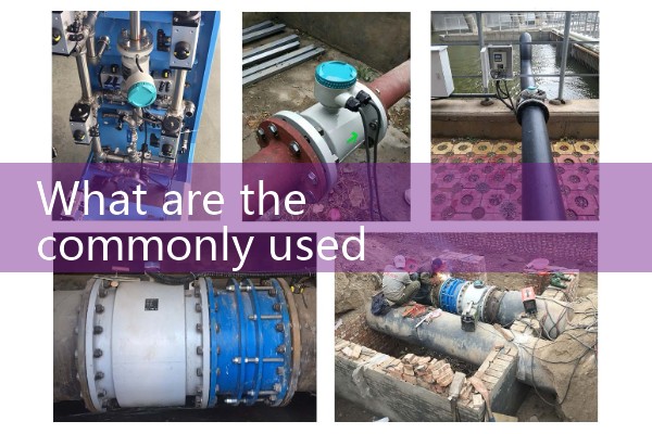
5, 4-20mA, etc.
III. Common fault solutions Fault phenomenon 1: No flow display or large data fluctuations Possible causes: Improper sensor installation position, coupling agent failure, bubbles or impurities in the pipeline.
. Solution: Adjust the sensor position again, supplement or replace the coupling agent; Check if the exhaust valve of the pipeline is working properly and install a silencer if necessary; Clean the inner wall of the pipeline. Fault phenomenon 2: Low signal strength Possible reasons: Poor contact between the sensor and the pipeline, severe sound attenuation of pipeline materials (such as cast iron pipes), and sensor damage. Solution: Re tighten the sensor and replenish the coupling agent; Replace with a sensor model suitable for high attenuation pipelines; Contact the manufacturer to replace the faulty sensor. Fault phenomenon 3: Large deviation in measurement values. Possible causes: incorrect pipeline parameter settings, fluid parameter changes not updated, temperature/pressure compensation not enabled. Solution: Check the parameter settings such as pipe diameter and wall thickness; Update fluid density, viscosity and other parameters through upper computer software; Enable tempera Hot Product
 Related AD