

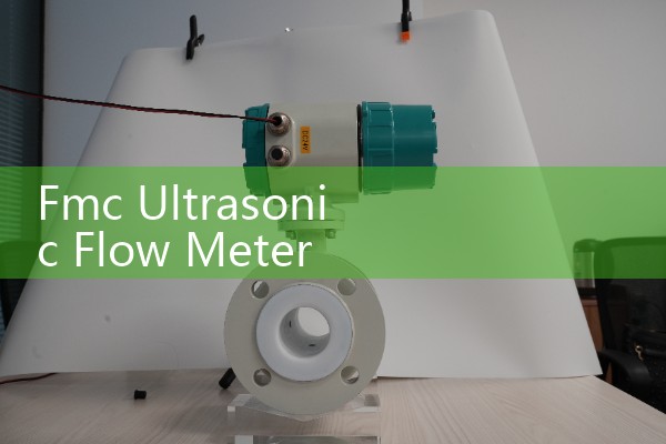
『Fmc Ultrasonic Flow Meter Maintenance: Field Troubleshooting and Transducer Verification Logs』Related information(clamp on meter|electromagnetic meter|venturi meterrotameter|orifice meter|ultrasonic flow meter|mass flow meter|coriolis mass flow meter|coriolis flow meter|magnetic flow meter|magmeter flow meter|magflow flow meter|mag meter flow meter|electromagnetic flow meter|vortex flow meter|turbine flow meter|thermal mass flow meter|thermal flow meter|rotameter flow meter)

Fmc Ultrasonic Flow Meter Maintenance: Field Troubleshooting and Transducer Verification Logs
Quick Answer: Fmc ultrasonic flow meter maintenance starts with clean transducers and stable power. Field troubleshooting should check signal strength, path blockage, cable resistance, and supply voltage before replacing boards. Keep a transducer verification log with baseline values after commissioning to spot drift early. Silver Instruments supports these checks for DN50 to DN1200 lines.
Maintenance Baseline for Fmc Ultrasonic Flow Meters
Here is the thing: ultrasonic meters rarely fail on their own. The process changes first. Fmc ultrasonic flow meter maintenance is not about opening the spool every week. Most service calls start with a process change, power drift, or wet transducer. Before you touch anything, record the diagnostic values.
Write down signal strength, gain, sound speed, and flow offset for each path. Put the values in the transducer verification log. Do not keep them on a sticky note. A pump station in Australia used a paper log for a DN200 raw water line. The operator caught a 9 percent gain shift two weeks before the meter alarmed.
For ATEX Zone 1 sites, complete the gas test and work permit before opening the housing. That step seems slow, but it prevents a bigger shutdown.
Field Troubleshooting Sequence
Check the power supply first. Many Fmc meters show a path error because the 24 V DC rail has sagged to 19 V. Measure voltage at the terminal block under load. A bench reading does not count.
For a healthy DN100 line at 50 percent flow, the 4 to 20 mA HART output should read about 12 mA. If the loop current is frozen at 20 mA, check the PLC input and the HART resistor before blaming the meter.
Next, inspect the ultrasonic transducer cables. Look for crushed jackets, water inside conduit, or loose connectors. A methanol plant in Indonesia found one cable at 18 ohms. The other cables measured under 2 ohms. That one bad cable caused random dropout.
If the signal is weak, check the transducer face. Do not use a wire brush. Wipe with a soft cloth and mild detergent. For clamp on transducers, remove old couplant and apply fresh acoustic grease. Recheck the signal after cleaning.
If all paths drop at the same time, suspect aeration, high solids, or a failed power module. In that case ask the operator what changed. A new pump or a filter bypass can throw off the ultrasonic signal in minutes.
Transducer Verification Logs That Work
A useful transducer verification log does not need too many columns. Start with date, time, tag number, fluid temperature, pressure, signal per path, gain per path, sound speed, and action taken.
Record the baseline after commissioning and after every cleaning or calibration. Compare new readings to the baseline band. A drift of more than 10 percent in gain or sound speed deserves attention. Do not ig
If the meter has a PT100 input, compare the displayed temperature against a separate gauge. A wild PT100 reading can shift sound speed and totalizer counts. That error shows up first in the log, not in the flow reading.
Keep one log per meter. We have seen teams mix up logs on identical DN150 sludge lines. That created false alarms and wasted a shutdown in a Philippine food plant.
Transducer Cleaning and Installation Checks
Dirty transducers are the most common fault in wastewater and brine service. A polymer plant in Vietnam had a DN80 Fmc style meter with a signal strength of 28 percent. Cleaning the transducer face with mild detergent lifted the signal to 74 percent.
On insertion transducers, check the O ring. A worn O ring lets process liquid reach the housing. The result is random signal loss or a rising gain value in the verification log.
On clamp on transducers, do not overtighten the strap. Too much force deforms the pipe and changes the acoustic path. Hand tight plus one quarter turn is enough for most pipe sizes.
Calibration and Factory Support
Silver Automation Instruments can help check Fmc style ultrasonic flow meters from DN15 to DN1200. Send us the tag number, fluid type, temperature in degrees Celsius, pressure in bar, pipe size in DN, and the current diagnostic readings. We will compare your values to expected ranges and suggest the next action.
For water and wastewater meters, a dry calibration check may be enough. For custody transfer or high temperature gas, a flow lab calibration is the safer route. We support service teams in Southeast Asia, Oceania, Latin America, Africa, and the Middle East.
Call Silver Automation Instruments at +86-25-68650347 or WhatsApp +86-25-52155837. For field support, add WeChat +86 15365082610.
FAQ
What is the first step in Fmc ultrasonic flow meter field troubleshooting?
Check the DC power supply at the meter terminal under load. Then read the diagnostic screen for signal strength, gain, and sound speed.
How often should transducer verification logs be updated?
Update the log during every planned maintenance, after every cleaning or calibration, and when any path alarm appears.
What signal strength is acceptable for an Fmc ultrasonic flow meter?
Most clean applications run above 60 percent signal strength. Values below 35 percent usually mean a dirty or misaligned transducer.
Can a dirty transducer cause a zero flow reading?
Yes. Coating, scale, or air bubbles can block the acoustic signal. The meter then reports zero or a path failure.
When should a flow meter be returned for factory calibration?
If the gain drift is over 10 percent and cleaning does not restore signal, the transducers or the board may need factory calibration.
 Hot News
 Related AD